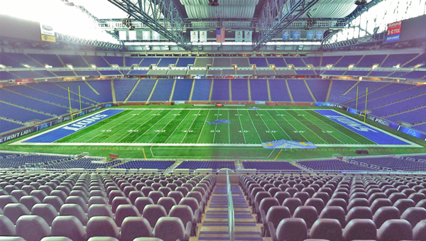
The ecosystem of technologies that capture 3D spatial data (Reality Capture) has changed drastically over the last several years. The data reality capture is often use to develop BIM design models or for construction coordination. One of the challenges for Architects, Contractors and ownersseeking the right value is the technology and planning to fit the scope and data use case. Often buildings with little or no existing data need the right type of reality capture defined to fit budget and usage scope. Requesting BIM to FM models or Digital Twin asset modelsin the current technology growth, can effect the capture and usage applications.
Perspectives will always change over time, and that’s especially true in the world of Reality Capture. I’ve been working in this realm now for 20 years and though reality capture is a relatively new term, in the past there wasn’t quite a defined description for this level of service. When I started, the only way to describe this type of work was in terms of a surveyor. As time went on and this laser scanning cat was let out of the bag, I’ve fulfilled roles as a mentioned surveyor, laser scanning tech, 3D Imagery Engineer, CAD drafter, scanning dude, VDC manager and probably and handful of other titles that all basically meant the same thing, and that was applying laser scanning technology to render out drawings CAD.
Now that laser scanning and Reality Capture are validated technologies and workflow methodologies have been refined well past the point of proof of concept, there is an array of options and deliverables that fall under this category. Not all construction projects require head to toe documentation with scanning, which may lead a project manager to consider different Reality Capture offerings. Here are some examples of the other facets of Reality Capture for Digital Transformation…
Project Coordination: Typically, the tool of this trade tends to be Navisworks. Imagine if there’s a baseline understanding of an interior space whether those dimensions have been acquired via laser scanning or tape measure only to be drafted or modeled out in Revit. Once that understanding of space has been acquired and all interior elements and obstacles are virtually visible in CAD, that’s when proposed design can be added, from any trade, fixture or element. That’s when the fun begins, as you’ll quickly be able to determine if the “mocked up design” will work or “clash” with design. It’s easy, you can see it!
Virtual Tours: Sometimes on the front end of a construction project, extensive mapping and understanding of the existing space may be required. However, in post construction the main benefit of a visualization may only be to look around, to confirm what’s been constructed, and to frankly show it off. That’s where Virtual Tours step in. It’s the ability to add somewhat of a Google Streetview to your project, to get people virtually moving within the space, because why not show off what’s been accomplished. It’s easy to use and lite as there’s no data to transfer, it’s web-based!
Static Laser Scanning: A more traditional form of laser scanning where the technology is tripod based and that scanner is moved through the scene to capture, and put laser scanning point cloud data on what’s important to the project and/or model.
Mobile Mapping: Similar to and based out of terrestrial or static scanning; mobile scanning is that same lidar technology on a moving platform. The standard benefit of applying this technology is gaining overall coverage on a project, though incremental accuracy may be the sacrifice, but that’s ok depending on the project need.
Digital Layout: By implementing laser scanning/reality capture, introducing benchmark targets onsite that are similarly located and placed in a Revit model, survey layout information can be utilized while onsite to directly related to and locate elements that exist in the model. By tying into targets and getting surveying equipment utilizing the same coordinate information that’s used in the model, it will enables the ability to “lay-out” or digitally locate elements that exist in the model, that need to be located and placed or built onsite.
Asset Management: Reality Capture and BIM work begins in producing the “As-built” conditions which are ultimately compared against proposed design, and then asset management steps into the process. This focus starts to add back all the pertinent information back into the model in regards to asset information such as in install date, manufacturer, record of an asset being serviced, and whatever other important information that needs to be linked back to that asset. Most standard BIM and Reality Capture efforts have certainly completed the interest of producing and similar 3d rendering models/representations, whereas asset management efforts put all of the necessary information back into that 3d model.
Establishing a consistent coordinate system: In Revit and in onsite: As multiple forms of spatial measurement technologies are introduced to a project site in enable and enhance building, they all need to be utilizing the same coordinate system to maintain an all together project accuracy. Laser scanners, total stations, distance meters, tape measures are all accurate measurement methodologies within their own relative need that they are supporting, but typically not as accurate when they are all used in conjunction together, on one project site. Reality Capture methodologies can help establish a consistent coordinate system that is seen and used in Revit and translated back onsite, where scan targets can be used as benchmarks that contain that same coordinate information that’s in Revit. By using these benchmarks, or creating co-similar Control Lines that are both onsite and in Revit, it make it much easier to “tie into” that same coordinate system that’s being referenced in Revit, despite whatever measurement tool your using everybody ties in the same way, using the same coordinates.
Scan-To-BIM Digital Transformation: When the scanning stops, that’ when the building begins so to speak. Whether the scanning is static or mobile, once it is brought into any number of 3D programs and the “points are turned into pipes” I always like to say; or wall, windows, doors or any other 3D elements, that’s when the rendered 3D model is produced from the point cloud, or hence the laser scanning data to a BIM deliverable.
Peter Abraham joined the team at PMC as of November 2020, bringing with him 20 years of focused experience in Reality Capture services in the AEC market, that range from data capture expertise and Virtual Design and Construction management.
Point clouds live somewhere in space, where they are in space are based on something called a coordinate system. In today’s post, we will keep the math to a minimum and approach coordinate systems from a practical, applied approach. In the world of CAD and point clouds, coordinate systems are defined by an X, Y, Z origin point, and a Z-axis rotation. When a point cloud is first registered, the origin and rotation are based on where the first scan was taken. This is seldom a good location as it is very arbitrary. To produce a useable point cloud, we need to put the point cloud on a rational coordinate system that the whole project team can use.
We assume that your building is relatively flat and level. If it is not, we need to talk. When we say relatively we mean that the main floors of the building would be flat within +/-1″ at any measured point.
How do you know what coordinate system to use? That is easy; PMC will ask a couple of questions to understand better what coordinate system is required for your project once scanning is complete. We do our best to break it down into a few simple questions.
Before we begin
Typically buildings will have some drawings or plans originating from construction. When there is existing CAD/BIM data of the building, it can be used as a reference for the point cloud data’s alignment. Generally, this is the preferred option for most teams. Aligning to your existing CAD/BIM data ensures that the existing data can be used without a need to shift it in the CAD/BIM environment.
If your building is ancient and there are no existing CAD/BIM drawings, no need to worry. We can work with that.
While AutoCAD and Microstation straightforwardly handle coordinates, Revit can have a Shared Coordinate added. If your Revit model is using Shared Coordinates, please let us know.
Have a survey file you want us to use? We should have already talked about that, oops. Please stop here and contact us.
It starts with a question
The first question you will be asked is, can you provide a CAD (DWG/DGN) or Revit model of the scope area? If you answer this yes, you will be almost done. We will have one more question for you. No worries though, even if you answer no, there are just a few more questions.
PDFs can not be used for alignment, only CAD/BIM data. If you don’t have a file, it’s not a problem. There are just a few more questions we’ll need to ask.
A simple Yes or No
If you chose yes to the first question, keep reading. If you chose no, skip to the next section.
You’ll be asked, do you want PMC to perform the best fit of the point cloud to the provided CAD or BIM file? What does that mean? It means that PMC will align your point cloud to the provided CAD or BIM file. Given the difference between the actual built environment and the assumed world of CAD, your point cloud will be centered within the CAD data and not aligned to any one benchmark. If you want to lock the point cloud to one specific point in the building, you need to pick no to this question. Some examples of this desire to have the origin be the center of a building column or a building corner.
You chose NO, now what?
You will be asked two additional questions to help define the origin and rotation of the point cloud. We’ll start by asking about the X/Y location then rotation. We provide the most common answers for you to pick from, but you can always choose to customize it. We know that every project of the built world is unique and will often require unique solutions.
X/Y
Q: For the X and Y-axis origin (North and Easting), how do you want the point cloud aligned?
A: Here, we ask you what point within the point cloud do you want X=0 and Y=0 to be. Typically this is some logical point in the building, like a corner. Sometimes it can be a known benchmark point like the center of a fire hydrant.
Rotation
Q: For rotation of the point cloud, please select what you would like.
A: In the first question, we locked in a 0,0 point, but we can rotate around that point. You likely don’t want your building to be rotated at 31.25 degrees, but what do you want it rotated too? The most common answer is to align the longest wall along the X-axis. You should consider how your project will fit your sheets and if having a project north or true north is important to you.
The Z-axis or Elevation?
We’re almost done here. We need to sort out elevation. What we need to know is, what do you want the elevation of the first floor you walk on when entering the front door to be? The most common answers are 0 and +100. Sometimes we are asked for sea level. We will take multiple measurements across that floor and average them to set the elevation.
If your building has multiple “main doors” to different floors or you think we may be confused by what the “front door” is, please reach out to us.
Wrapping it up
You’re done! We know how to align your data and it will be in your hands shortly! Have concerns still? Worried we don’t know what you mean? No problem, the form is not meant to replace talking to one of us. If you have any concerns at all we are here to help. Please feel free to reach out at any time to the team at PMC.
Well, What is it? Terrestrial laser scanning (TLS) is a form of measuring with a tripod-based LIDAR (light detection and ranging) instrument used to capture high accuracy data of buildings and other objects.
What is it used for?
TLS is used for a large variety of different applications, including capturing the flatness of a wall, preserve the conditions of a crime scene or accident, document the faꞔade of a large building for pre-fab architectural paneling, analyzing the shape of a vessel, volumetric stockpile surveys and many more.
Leica Scanner at a Bridge
How does it work?
Terrestrial Laser Scanners works by emitting an invisible laser to measure 3D points the same as a survey total station would. The difference is the scanner’s ability to measure its entire scene and the speed at which the measurements are taken.
The laser field of view is 310 degrees vertically and 360 degrees horizontally. The laser scanner will rotate upon the tripod and spin the mirror at the same time to capture the full scene. Each scan takes about 3-7 minutes, depending on the resolution.
What Does a Terrestrial Laser Scanner measure?
Terrestrial Laser Scanners measure everything in the line-of-sight of the laser. The smallest details like the texture of brick, the leaves on trees, and the metalwork of ornate hand-railings are picked up in the scans.
Scan of a museum
What is the accuracy of the Terrestrial laser scanner? Is it any better than a pro-3D camera?
Absolutely, terrestrial laser scanners can measure points as accurate as 3mm at 30 feet. A standard pro-3D camera cannot achieve less than an inch of accuracy. The resulting “point clouds” from the scanner are extremely high-resolution with points in spaced very close together, so close that the result of a scan looks just like a photograph.
The higher the resolution the slower the scanner will rotate making the resulting point cloud more detailed. The faster the scanner rotates the less time the laser has to document to small changes creating a lighter point cloud.
The Resolution of the scanner does not always directly affect the resolution of the “project point cloud”. For example, scanning a single wall with a handful of low resolution scans the resulting point cloud will be a higher resolution because of the number of points that accumulate from more than one low res scan.
Grey-scale Factory Scan
Color or Black and White?
Depending on the need or conditions of the project, laser scanning can be conducted in absolutely no light. This makes it possible to measure and see things in places of absolute darkness. When scanning in dark conditions, the scanner is unable to pick up color unless artificial light is added, but the resulting point cloud imagery looks almost like night vision. Everything that was once very dark will be brightly visible in the 3D imaginary.
What are the benefits of using terrestrial laser scanning?
Benefits in Architecture
Capture the “as-is” conditions of a building quickly, accurately, and with little to no disruption. Photorealistic imaging and 3D visualization of different aspects of buildings to create views never seen before. 3D data can be used in all common CAD programs. FARO WebShare Cloud for sharing the scan data via the internet simple, secure, and can be used anywhere online. The resulting point clouds can be precisely modeled in Autodesk Revit.
3D modeling and laser scanning of a historic fountain
Benefits in Construction
Laser Scanning in construction can offer fast and cost-effective documentation of the entire construction process. Seamless capture and monitoring is critical for construction progress for legal and technical documentation, precise dimensional check of complex components such as free-form shape elements, documentation of deformation processes and monitoring of countermeasures., project coordination to help improved multi-trade project collaboration. Capturing scans at all phases of construction can aid in the case of final building inspections by being able to go back and visualize the entire construction process start to finish.
Structural Steel Clash Detection
Benefits in Property Management & Facility Maintenance
Building information models (BIM) is taken another step further here at PMC. We interject valuable asset information right into the living model. This way your facility can be on the cutting edge of maintenance and efficiency by utilizing autonomous features right through the model.